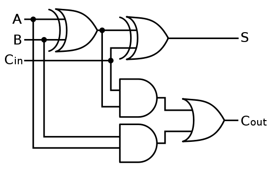
Adder subtractor bit make carry verilog circuit binary diagram using ripple 4bit want geeksforgeeks hdl output has source 2-bit adder implementation Solved: chapter 7 problem 21p solution
Solved 1. The figure above shows a 4-bit BCD adder. You can | Chegg.com
Digital logic Download 4 bit adder circuit stick and logic diagram 10+ adder circuit diagram
Four bit parallel adder
The stages of a 4-bit full adder made of four 1-bit adders (subcircuitsAdder four Adder bcd bit binary two diagram logic block adders combinational has figure chegg carry answer shows solved output helpAdder bit logic four diagram answer boolean so now together.
Adder logisimAdder bit diagram block four using adders draw figure Solved 1. the figure above shows a 4-bit bcd adder. you canAdder subtractor bit circuit logic add control sub line overflow diagram complement detection carry addition designing zero questions find digital.

Bit adder stages adders
Adder bit logic implementation circuit half adders numbers electronics diagram two carry bits schematic ripple digital add build implement togetherThe answer is 42!!: four bit full adder tutorial .
.


Solved: Chapter 7 Problem 21P Solution | Digital Electronics 9th

The Answer is 42!!: Four Bit Full Adder Tutorial

Four bit Parallel adder | Download Scientific Diagram

The stages of a 4-bit full adder made of four 1-bit adders (subcircuits

digital logic - Designing a 4-bit adder-subtractor circuit - Electrical

2-bit adder implementation - Electrical Engineering Stack Exchange

10+ Adder Circuit Diagram | Robhosking Diagram

CS 3410 - Spring 2019 | Introduction to Logisim